Fundamentals of microfluidic mixing for LNP synthesis

The recent progress of microfluidics mixing technologies (micromixers) has been key to the recent success of the covid-19 LNP-mRNA-based vaccines.
Micromixers permit the very fine control of the mixing speed of 2 liquids phases, which is one of the key factors to determine the final lipid nanoparticles physiochemical parameters, as introduced in our LNP formation mechanism review.
Combined with the unique capability offered by microfluidics in terms of scale-up from small (µL) to large (L) volumes and fluidic system automation, the use of micromixer for LNP synthesis permit the uttermost control oits physichochemical characteristics including size, PDI, zeta potential… all throughout the drug development process.
This review aims at introducing the fundamentals of microfluidic mixing for LNP synthesis followed an overview of the available microfluidic mixing technologies with a focus on their working principle and efficiency.
Mixing fundamentals in microfluidics
Laminar flow results in many counter-intuitive behaviors, with mixing being one of the most drastic examples. Cambridge dictionary defines the verb ’to mix’ as the action of combining different substances so that the results cannot easily be separated into its parts: mixing of miscible liquids is generally considered an entropic process that is irreversible.
In absence of any turbulence, mixing can be driven by two forces: diffusion and convection. In continuous flow, both processes are always happening at the same time. One might overpower the other and it is interesting to quantify their importance relative to one another. Derived from Fick’s law and continuity equations, the evolution of the concentration of a molecule with time is given by the diffusion-convection equation:
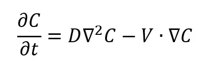
From the normalization of this expression, another very important dimensionless number comes into play, the Péclet number (Pe), which describes the relation of convective to diffusive flows:
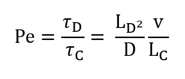
where LD is the characteristic diffusion distance in m, D is the diffusion coefficient in m2/s, LC is the characteristic flow distance in m, and v is the fluid flow velocity in m/s. Thus, if Pe ≪ 1, then the convection time is much larger than the diffusion time and mixing by diffusion prevails, while if Pe ≫ 1, the diffusion time is much larger than the convection time and mixing by convection prevails. Purely diffusive mixing is generally slow. Typical diffusion rates for small ions are in the range of 2 × 10^3 µm2/s while cells of a size of 10 µm diffuse about 2×10^−2 µm2/s, illustrating that mixing, reaction kinetics and other operations in microfluidics depend strongly on the species of interest. In most microfluidic devices fluid interfaces are largely parallel to the fluid velocity, which simplifies handling because diffusion occurs rather slowly. If mixing is desired, Pe becomes more important and can influence different mixer designs implemented.
Microfluidic mixing efficiency
The first step before choosing a suitable design for the microfluidic chip and setup is to determine what is important for the final application. In the context of lipid nanoparticle synthesis, the goal is to reach the finest control of the mixing speed. The most commonly used parameters to characterize the mixing speed are the mixing time and length.
Mixing time and length
The mixing time, tmix, is defined as the residence time of the fluid before it reaches a certain mixing index, usually over 90%. The mixing time and mixing distance, dmix, are directly linked to the average flow speed, vm, such that : ![]()
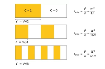
The mixing time can be extracted from the analytical expression of the concentration C(x,t) and the mixing index. In the case of purely diffusive mixing, the mixing time scales proportionally with the square of the diffusion length l and inversely proportional to the diffusion coefficient : 
The diffusion length l can be understood as the biggest distance a molecule has to travel to reach a low concentration zone. As illustrated below figure dividing the same amount of fluid into multiple layers and interfaces allows for reducing the mixing time very efficiently. In this simple configuration, tmix is inversely proportional to (n + 1)2 where n is the number of interfaces between fluid A and B. Thus, mixing is 16 times faster when 7 interfaces are present instead of 1. We will see in the next section how some micromixers integrate this strategy into their design to enhance mixing.
Choice of micromixer for lipid nanoparticle synthesis
As we have seen previously, processes in laminar flows are dominated by viscous effects and no turbulence comes into play to increase the mixing of two miscible phases. For this reason, and because a wide range of applications relies on mixing, numerous different microfluidic systems for mixing have been designed.
Micromixers can be divided into two categories: passive and active mixers. Passive mixers solely rely on the channel geometry to perform controlled mixing while active mixers use external forces (e.g. magnetic stirring, acoustic waves, electromagnetic waves or pressure perturbations). We will now review some of the mostly used micromixers:
Passive micromixers
Diffusive mixers
Diffusive mixer is the first and most simple generation of mixers, they basically rely on the creation of an interface between the liquids, leading to diffusion between them.
T- and Y-shaped micromixers
Mixing in these designs is based on purely diffusive mixing and those micromixers typically have a mixing length d95% proportional to Pe. This means that for a typical microchannel geometry, a very long channel will be required to fully mix two fluids at high flow speeds. Lower flow speeds will reduce the mixing length but the mixing time will remain similar following the mixing time and length equation. This geometry can however be interesting to generate flow based-gradients, in applications that do not require a small residence time or fast mixing. Hsieh et al. demonstrated that the wider the angle between the two inlet channels, the more efficient the mixing.

T and Y shaped micromixers
Hydrodynamic flow focusing (HFF) microfluidic mixers
This method also relies on purely diffusive mixing. By squeezing a middle stream of fluid A between two streams of fluid B, the mixing time of B in A is greatly reduced by decreasing the characteristic diffusion length l, as seen in the previous section. The equation for the mixing time in a 2D HFF design becomes :

2D Hydrodynamix flow focusing/HFF mixing time
where Wf is the width of the focused stream, W is the width of the microchannel and FRR is the flow rate ratio between the two fluids. This equation clearly shows that the mixing time decreases when the FRR increases. The total flow rate has no impact on the mixing time. This ensures a very reliable and predictable continuous flow mixing even at relatively high flow rates. When 2D HFF is used to control chemical reactions between fluid A and B, one problem that often arises is the adsorption or absorption of products on the microchannels walls. To solve this issue, 3D HFF designs have been developed to ensure that the products of the reaction are confined in the center of the channel and never in contact with the boundaries. However, as 3D HFF often relies on the use of embedded glass capillaries which need to be carefully aligned during their assembly, this technique especially suffers from challenges towards its industrialization. In both cases, a high amount of fluid B is required to focus the middle stream, which in some case can be problematic if reagent B is scarce and expensive. Another drawback of this method is that fluid A gets heavily diluted in fluid B, since better mixing performances occur at high FRR.

2D and 3D Hydrodynamix Flow Focusing mixer
To conclude on diffusive mixers, these offer good first approach to mixing, however due to their reliance on flow rate ratio as a main control paramters, they offer both less flexibility on the final nanoparticle characteristics control and much lower yield due to the high flow rate ratio typically used.
For this reason, new generation of more advanced passive mixers such as herringbone and baffled have been developped, showing overall between nanoparticle physiochemical characteristics control (size, PDI...)
Conclusion on diffusive mixers
To conclude on diffusive mixers, these offer a first approach to microfluidics mixing. However due to their reliance on flow rate ratio as a main control parameter, they are not best suited for nanoparticle synthesis as they offer offer both less flexibility on the final nanoparticle characteristics control and much lower yield due to the high flow rate ratio typically used.
For this reason, new generation of more advanced passive mixers such as herringbone and baffled have been developped, showing overall between nanoparticle physiochemical characteristics control (size, PDI...)
Looking to synthesize nanoparticles using microfluidics?
Discover our innovative and user-friendly nanoparticle synthesis platforms
Chaotic mixers: Herringbone
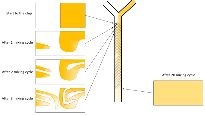
Staggered herringbone micromixers belong to the class of chaotic mixers, where the geometry of the microchannels is designed to enhance mixing by advection rather than diffusion. In particular, the strategy employed here is to imprint a pattern of grooves in the microchannel. This will force the particles of fluid to follow a curved path while traveling in the microchannel, as illustrated in the below figure. This folding and unfolding behavior of the fluid is characteristic of chaotic flows. The use of the word chaotic here might be misleading and it is important to keep in mind that this flow regime is still laminar and Re is typical < 2000. Indeed, the flow path remains unchanged as long as the laminar Stokes flow condition is respected, and this is important to keep the repeatability of the mixing process in steady-state operation.
The first staggered herringbone micromixer was developed in 2002 by Stroock et al. and has since been one of the most famous micromixers. The group demonstrated that at high Pe the mixing length, d95%, of these micromixers is growing logarithmically with Pe such that:
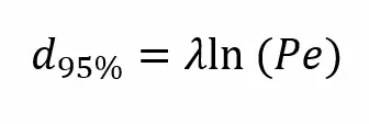
with λ a characteristic length determined by the flow trajectories, typically in the order of magnitude of a few mm. Since Pe is growing linearly with the flow speed, increasing the flow velocity leads to a decrease in mixing time. For example, increasing the speed by a factor 10 only increases the mixing length by a factor 2.3 in a herringbone micromixer and the mixing time reduces by a factor 0.23 (according to mixing time equation). This is why the total flow rate used in this type of micromixer has a high impact on the mixing time.
Obstacles-based microfluidic mixers
As stated in their name, these mixers rely on the presence of obstacles, sometimes placed periodically, or formed by features of the microchannel wall itself, called "baffles". Placing barriers and obstacles in a microchannel usually enhances mixing by creating secondary flows or vortices behind the barriers, at relatively high Re. However, a compromise has to be found for each design to enhance mixing without adding too much flow resistance, which would limit the use of the micromixer to a reduced range of flow rates.
One of the first passive micromixers to be using that strategy to enhance mixing was developped by Wang et al., in 2014. Triangle baffles (see A in the figure below) were patterned in the PDMS microchannel with soft lithography techniques and the mixing index was evaluated at the outlet of the chip, both experimentally and with numerical simulation on a wide range of Re (0.1 to 500). This design was found to be 8 times more effective than a T-junction mixer, at Re = 500.
Baffle micromixers also rely on the creation of secondary flows in the laminar flow path. Kimura et al. demonstrated the practical use of such micromixers for lipid nanoparticle generation. The group demonstrated that the baffle’s geometry has a high impact on the mixing time and that the baffle mixer has a mixing time approximately 10 times shorter than a chaotic herringbone-based micromixer.
In a recent study, the mixing of the baffle mixer was enhanced by including a curvilinear path in the microchannel which submit the flow to opposing centripetal forces (see B in the figure below). The design was named periodic disturbance mixer and the mixing was mainly influenced by Re and the Dean number (De):
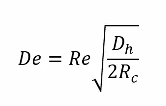
where Dh is the hydraulic diameter of the microchannel and Rc is the radius of curvature of the curvilinear regions. The flow through these opposing radius of curvature is characterized by the presence of Dean vortices at high flow rates. No analytical expression for the mixing time was reported in the literature for this type of micromixer but Lopez et al. found it to be < 10 ms at a TFR of 500 µL/min and a FRR of 9 : 1. They also observed a clear decrease in the mixing time with the increase of flow rate, which increased both Re and De, until a certain critical De was reached.
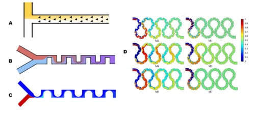
Droplet-based and segmented flow microfluidic mixers
In droplet-based mixers (A), chaotic mixing of two or more miscible fluids can be achieved in droplets dispersed in a continuous oil phase. Flowing droplets are characterized by the presence of inner vortices which are symmetrical and aligned with the direction of the flow in a straight channel configuration. To break the symmetry in those vortexes, turns or other perturbations need to be introduced in the flow path, a serpentine channel geometry is generally used for this purpose. One advantage of this technique is that the potential products resulting from the mixing of reactants, such as nanoparticles, are not in direct contact with the microchannel walls and the chip fouling is thus greatly reduced. This also allows to barcode the different droplets and test different formulations continuously. Cross-contamination in sequential change of formulations is reduced due to the elimination of the Taylor-Aris dispersion effect characteristic of continuous laminar flows.

Segmented-flow mixers (B) have similar designs than droplet-based ones but here a non-miscible gas is employed as the dispersed phase. Segmenting the flow with gas bubbles creates the formation of vortexes in the liquid slugs which result in a flow regime called ’Taylor flow’. A thin layer of liquid is separating the gas bubbles from the microchannel walls and liquid backflow behind the gas bubbles leads to the formation of Taylor vortexes, which greatly enhance the mixing performance in the liquid slugs. The occurrence of these vortexes is prevalent with certain flow conditions that are best described by the Capillary number (Ca) : Ca = μ vb / γ
where µ and γ are the dynamic viscosity and surface tension of the liquids while vb is the average gas bubbles velocity. Relatively low Ca is required to ensure the presence of vortexes. Larger gas bubbles increase the vortex velocity by reducing the slugs size, which improves the convective mixing. Just as in droplet generation systems, the bubbles and liquid slugs size can be tuned with the flow rate ratio between both phases. Although a high throughput of highly mixed fluids can be produced with this technique, using this technique to produce particles leads to channel fouling and clogging. This effect can be managed with improved microfabrication techniques and surface treatment to smooth microchannels’ surfaces and reduce particle adsorption
Other types of passive micromixers for LNP synthesis
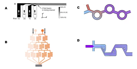
Other alternative methods can also be used for the micromixng synthesis of LNP. Lamination mixers use a fluidic network to essentially split the flow from the inlets and recombine it into a common channel, thus increasing the number of interfaces and reducing the diffusion length. One of the first examples of a lamination mixer was developed by Bessoth et al. in 1999, where they used microstructures to split the flow of the fluids to be mixed. With their design, they reached mixing times down to 15 ms at flow rates between 1-200 µL/min. Another simpler, design is illustrated below in figure A and was developed in 2001 for time-resolved infrared (IR) spectroscopy. The design was later improved to reach mixing times in the order of 1 ms.
Tree-shaped mixers, as illustrated on figure B are best suited to create very precise and controlled gradients in wide chambers, which can be used as lab-on-chip devices to test the effect of a drug or a toxic chemical at different concentrations. The first attempt was created in 2000 by the famous Whitesides group and similar designs now exist in very diverse models, with two or more fluids being gradually mixed by successive divisions of the flow. This type of mixer can also be found commercially, and recent studies have published tools that allow easy tree-shaped chip design optimization for lab-on-chip experiments.
Stepping away from gradients, bifurcating or split-and-recombine mixers such as illustrated in figure C are starting to make their way into the passive micromixers club. A few studies have been performed on this type of micromixer, which consists of splitting a continuous co-flow of fluids along circular paths and then recombining them. The mixing was enhanced by adding an asymmetry in the circular branches, as was much exploited by Zou et al., in a recent study published in 2021.
The last mixer is using a similar strategy as the bifurcating mixers and was derived after the Tesla valves that were originally designed by Nikola Tesla, as passive one-way valves, and patented in 1920. The design shown in Figure D is actually a combination of a 2D flow-focusing design with a Tesla micromixer and has been used for composite nanoparticle synthesis. With this design, a mixing time of 10 ms was reached but the maximum flow rate that could be achieved was 50 µL/min.
Active Microfluidic Mixers
Active mixers use external energy to enhance mixing in a microfluidic chip. Here we will only present acoustofluidic mixing but other techniques based on electric field or magnetic field can be found in the literature. The advantage of such mixers over their passive counterparts is that the degree of mixing can be tuned by changing the magnitude of the external field applied, hence the mixing efficiency can be adapted for a wide range of flow rates. A drawback is that these micromixers generally require more complicated fabrication steps and are energy intensive.
Acoustofluidic mixers
Accoustofluidic micromixers use sound waves, sometimes associated with flexible features in the microchannels, to generate vortexes which will greatly enhance the mixing. In a recent study, Pothuri et al. performed numerical simulations to demonstrate how standing acoustic waves were efficiently decreasing the mixing time in various flow configurations. They applied the bulk waves parallel or transversely to the flow in a flow-focusing or Y-junction configuration. In the Y-junction case, with a FRR of 1:1, the mixing time was 10 times faster with the application of a transverse acoustic wave and more remarkably, another 5 times faster when the waves were applied parallel to the liquid-liquid interfaces. To ensure a sufficient residence time of the fluid in the microchannel for complete mixing, a maximum flow rate threshold was set at Qmax = A.Lch / tmix , with A the cross-section of the channel and Lch its length.
For nanoparticle generation, the time scale required for the mixing time is in the order of ms. Even though the previously described method does not require any complicated microfluidic design, the minimal mixing time reached is theoretically in the order of seconds.
The parameters impacting the mixing performances of such devices are mainly the driving voltage of the acoustic transducer, the feature’s geometry and type (sharp edges, bubbles, or a combination of both), the thickness of the glass slide, and the total flow rate. Zhao et al. combined an HFF channel geometry with periodic sharp edges, in a similar way as a baffle micromixer, and acoustic waves. This allowed for reducing the mixing time from 4 ms for the classic HFF geometry to less than 3 ms for the acoustic mixer. Another advantage of this technique for the production of nanoparticles (NP) is the reduced aggregation and chip fouling with NP because of the ultrasound waves.
Conclusion on the microfluidic mixing technologies for LNP synthesis
The main takeaway from the above discussion is that numerous microfluidic mixing methods are available for the synthesis of lipid nanoparticles. Among them, the ones allowing for the tuning of the mixing speed should be preferred as they offer the possibility of better controling the final LNP physiochemical parameters. The herringbone chip design is currently the most used one as it is both a relatively simple design and allows for the finest control of the final LNP size, however new designs such as baffled or recombination are showing promising results. To learn more on how to use it with a microfluidic setup, check our review on lipid nanoparticle synthesis with microfluidics.
